Rotation:
angle: rotate negated angle
axis: negate z component
https://butterflyofdream.wordpress.com/2016/07/05/converting-rotation-matrices-of-left-handed-coordinate-system/
https://www.evl.uic.edu/ralph/508S98/coordinates.html
Translation:
negate z component
Then you have things like SteamVR pose to Unity pose conversion in SteamVR_Utils in Unity's SteamVR plugin:
public RigidTransform(HmdMatrix34_t pose)
{
var m = Matrix4x4.identity;
m[0, 0] = pose.m0;
m[0, 1] = pose.m1;
m[0, 2] = -pose.m2;
m[0, 3] = pose.m3;
m[1, 0] = pose.m4;
m[1, 1] = pose.m5;
m[1, 2] = -pose.m6;
m[1, 3] = pose.m7;
m[2, 0] = -pose.m8;
m[2, 1] = -pose.m9;
m[2, 2] = pose.m10;
m[2, 3] = -pose.m11;
this.pos = m.GetPosition();
this.rot = m.GetRotation();
}
2017年6月8日 星期四

2017年5月23日 星期二
2017年3月22日 星期三
Unity depth mask using additional camera
reference
sample unity package
Note: this trick doesn't work with Unity SteamVR plugin's CameraRig
Note: this is a different implementation from the depth mask from unity wiki
The basic idea of depth mask is just like normal z-test. You use transparent objects (say mask objects) that are closer to the camera so other objects behind the mask objects will not pass the z-test and not be rendered.
However the problem is that under the same camera rendering, transparent objects can't be considered as passed z-test when opaque objects are behind them.
So the trick is just like the reference link above, use another camera (say camera2) that draws masked object after previous camera(say camera1) rendered the transparent masks.
In this case, camera1 draws first and makes transparent objects write to the z-buffer, then when camera2 is drawing, since the z-buffer is occupied by the transparent objects, the object behind the mask will fail the z-test.
Apparently, the camera1 and camera2 need some settings to achieve the mask effect. Just like the reference link, camera1 needs to render before camera2, so the "depth" property in Unity camera needs to be setup. Just set camera2's depth be larger than camera1's depth to achieve the rendering order.
Then since camera2 draws on top of camera1, camera2's "clear flags" needs to be set as "Don't clear".
Make sure that camera2 has exactly the same camera properties and 3D objects settings as camera1(transforms, fov...), otherwise the rendered scenes will not match.
Add transparent objects into the scene as mask. The transparent objects need to write into the z-buffer, you can use the shader code below to achieve this.
Finally, add a User Layer in Unity (say MaskedObject as the layer name), set masked object to be in the MaskedObject layer, set camera2's culling mask to MaskedObject, then try to move the masked object behind the transparent masks.

here is the result

the moving cube is masked at certain positions, those positions actually are occupied by transparent cubes and the transparent cubes occlude the masked cube.
the shader code for transparent mask object
sample unity package
Note: this trick doesn't work with Unity SteamVR plugin's CameraRig
Note: this is a different implementation from the depth mask from unity wiki
The basic idea of depth mask is just like normal z-test. You use transparent objects (say mask objects) that are closer to the camera so other objects behind the mask objects will not pass the z-test and not be rendered.
However the problem is that under the same camera rendering, transparent objects can't be considered as passed z-test when opaque objects are behind them.
So the trick is just like the reference link above, use another camera (say camera2) that draws masked object after previous camera(say camera1) rendered the transparent masks.
In this case, camera1 draws first and makes transparent objects write to the z-buffer, then when camera2 is drawing, since the z-buffer is occupied by the transparent objects, the object behind the mask will fail the z-test.
Apparently, the camera1 and camera2 need some settings to achieve the mask effect. Just like the reference link, camera1 needs to render before camera2, so the "depth" property in Unity camera needs to be setup. Just set camera2's depth be larger than camera1's depth to achieve the rendering order.
Then since camera2 draws on top of camera1, camera2's "clear flags" needs to be set as "Don't clear".
Make sure that camera2 has exactly the same camera properties and 3D objects settings as camera1(transforms, fov...), otherwise the rendered scenes will not match.
Add transparent objects into the scene as mask. The transparent objects need to write into the z-buffer, you can use the shader code below to achieve this.
Finally, add a User Layer in Unity (say MaskedObject as the layer name), set masked object to be in the MaskedObject layer, set camera2's culling mask to MaskedObject, then try to move the masked object behind the transparent masks.

here is the result
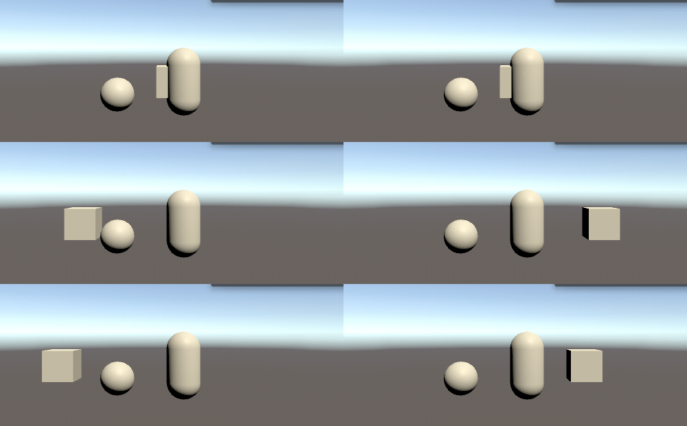
the moving cube is masked at certain positions, those positions actually are occupied by transparent cubes and the transparent cubes occlude the masked cube.
the shader code for transparent mask object
Shader "SimpleTransparentZWrite"
{
 SubShader
 {
  Tags{ "Queue" = "Transparent" }
  Pass{
   Blend SrcAlpha OneMinusSrcAlpha
   ZTest LEqual
   Cull Back

   ZWrite On
   CGPROGRAM
   #pragma vertex vert
   #pragma fragment frag
   #include "UnityCG.cginc"
   struct appdata {
    float4 vertex : POSITION;
   };
   struct v2f {
    float4 pos : SV_POSITION;
   };
   v2f vert(appdata v) {
    v2f o;
    o.pos = UnityObjectToClipPos(v.vertex);
    return o;
   }
   half4 frag(v2f i) : SV_Target{
    return half4(0,0,0,0.0);
   }
   ENDCG
  }
 }
}
2017年2月12日 星期日
Notes about depth texture(using Unity shader code)
Depth texture used for effects like fog normally uses camera's depth texture, the shader code is as the following:
float depth01 = Linear01Depth(UNITY_SAMPLE_DEPTH(tex2D(_CameraDepthTexture, i.depthUV)));
Then you get the float in the range (0,1) for the depth value.
But the problem is that the depth texture of camera doesn't contains information about transparent objects, so we need to use fragment's depth in clip space, the shader code is as the following:
struct appdata
{
float4 vertex : POSITION;
half2 texcoord : TEXCOORD0;
};
struct v2f
{
float4 pos : SV_POSITION;
float2 uv: TEXCOORD0;
float2 depthUV : TEXCOORD1;
float3 cameraToFarPlane : TEXCOORD2;
float4 screenPos : TEXCOORD3;
};
v2f vert(appdata v)
{
v2f o;
o.pos = UnityObjectToClipPos(v.vertex);
o.screenPos = ComputeScreenPos(o.pos);
...
}
fixed4 frag (v2f i) : SV_Target
{
float depth01 = i.screenPos.w / (_ProjectionParams.z - _ProjectionParams.y);//normalize to the range(0,1)
//i.screenPos.w: depth(z) in camera space, range(n, f), i think(could be wrong). Please check http://blog.csdn.net/zhao_92221/article/details/46844267 and http://www.songho.ca/opengl/gl_projectionmatrix.html for details. I guess unity uses projection matrix to map (n,f) to (0,1), could be wrong
//_ProjectionParams.z - _ProjectionParams.y: camera far - near
}
One use case of these two different values is that you can use it to measure the thickness of the transparent objects(e.g. the depth of water object). Simply use the depth for fragment in clip space to subtract the depth in camera's depth texture.
float depth01 = Linear01Depth(UNITY_SAMPLE_DEPTH(tex2D(_CameraDepthTexture, i.depthUV)));
Then you get the float in the range (0,1) for the depth value.
But the problem is that the depth texture of camera doesn't contains information about transparent objects, so we need to use fragment's depth in clip space, the shader code is as the following:
struct appdata
{
float4 vertex : POSITION;
half2 texcoord : TEXCOORD0;
};
struct v2f
{
float4 pos : SV_POSITION;
float2 uv: TEXCOORD0;
float2 depthUV : TEXCOORD1;
float3 cameraToFarPlane : TEXCOORD2;
float4 screenPos : TEXCOORD3;
};
v2f vert(appdata v)
{
v2f o;
o.pos = UnityObjectToClipPos(v.vertex);
o.screenPos = ComputeScreenPos(o.pos);
...
}
fixed4 frag (v2f i) : SV_Target
{
float depth01 = i.screenPos.w / (_ProjectionParams.z - _ProjectionParams.y);//normalize to the range(0,1)
//i.screenPos.w: depth(z) in camera space, range(n, f), i think(could be wrong). Please check http://blog.csdn.net/zhao_92221/article/details/46844267 and http://www.songho.ca/opengl/gl_projectionmatrix.html for details. I guess unity uses projection matrix to map (n,f) to (0,1), could be wrong
//_ProjectionParams.z - _ProjectionParams.y: camera far - near
}
One use case of these two different values is that you can use it to measure the thickness of the transparent objects(e.g. the depth of water object). Simply use the depth for fragment in clip space to subtract the depth in camera's depth texture.
2016年7月5日 星期二
some old stuff

bump mapping by GLSL, but I didn't understance the relations between tangent, normal and binormal that time...

an image rendered by ray tracing, totally forgot how I made photon mapping work...
3D drawing on Android
2016年4月18日 星期一
NDC to world coordinates
here is the original link
link


link
We transform it to clip space by multiplying it with our projection/modelview matrix.
Then move on to device coordinates by dividing with  .
.
.
So the problem we face is: given , , ,
, , ,
and given  as an input and
  as a constant, calculate
  .
.
as an input and as a constant, calculate .
Let’s walk through it. Invert the first step:
Now let’s see what we can do with the second equation.
Let’s use this syntax to indicate a 4-vector formed by combining a 3-vector and a fourth number:
substitute 
insert into our earlier equation
And note that since matrices are linear transforms, we can pull that  in front of the matrix multiply:
in front of the matrix multiply:
So it seems we run into a wall. is lost, right? Don’t give up hope: we haven’t used the third of our initial givens yet.
is lost, right? Don’t give up hope: we haven’t used the third of our initial givens yet.
So let’s look at just the component of that last equation there:
component of that last equation there:
Divide:
And insert into the equation that previously gave us trouble:
Or in other words:
訂閱:
文章 (Atom)